I. What is LiDAR self-motion distortion?
LiDAR measures the distance and direction of surrounding objects by emitting laser beams and measuring relative location of a vehicle to an obstacle. When there are enough laser beams, these laser points will form a point cloud to plot the 3D information. This is what we often call point cloud data.
For most LiDARs, although the laser is transmitted and received quickly, each point that makes up the point cloud is not generated at the same moment. Generally, we output the data accumulated within 100ms (corresponding to a typical value of 10Hz) as one frame of the point cloud. If the absolute location of the LiDAR body or the body where LiDAR is mounted changes during this 100ms, the coordinate system of each point in this frame point cloud will be different. Intuitively, this frame of point cloud data will be "distorted" and will not truly correspond to the detected environmental information. It is like the case of taking a photo, if your hand shakes, the photo will be blurred. This is the self-motion distortion of LiDAR.
II. Essence of self-motion distortion and its calibration
Let's take a look at what self-motion distortion is.
The pattern of the self-motion distortion of LiDAR point cloud is related to its scanning method. For example, each frame of traditional 360-degree mechanical LiDAR is scanned from the points around the center of the LiDAR (100ms). When the LiDAR body or the host vehicle is stationary, the scanning start and end points will have a better matching (the coordinate origin always remains the same). And when the LiDAR or vehicle is in motion, the self-motion distortion will occur and the data for one round will be distorted, causing the surrounding points are longer matched (different points have different coordinate origins).
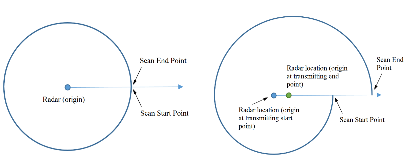
Figure 1. 360-degree mechanical LiDAR self-motion distortion schematic
Let's further analyze the essence of this phenomenon.
To put it simply, the self-motion distortion in the LiDAR point cloud is essentially the result of a different coordinate system for each point in a frame.
In the figure below, the left figure p1~p3 indicates the three location points scanned by LiDAR consecutively, which are co-linear in the real world. However, due to the "violent" motion of the LiDAR in one frame, the LiDAR scanned three points in three different attitudes, as shown in the middle figure. Therefore, in the final point cloud obtained (the rightmost figure), these three points are actually in different coordinate systems and no longer appear to be co-linear.

Figure 2. Point cloud coordinate system changes
Figure 3 gives an example of actual application.
Self-motion distortion happened when a vehicle is equipped with Livox LiDAR and makes a U-turn: Both the wall and the vehicle in the distance produced delamination due to the rapid rotation of the vehicle.
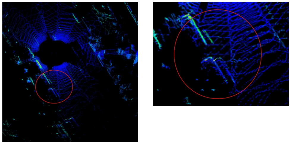
Figure 3. Point clouds of parked vehicles on the roadside are delaminated due to vehicle motion
So, how to amend the self-motion distortion? Apparently, if we drive the car slowly enough ...
Of course not, we need to convert the coordinate system of all points in one frame to the same coordinate system where the first point p1 is located as shown in Figure 1, which is essentially a compensation for the motion of the LiDAR.
We use p1i to indicate the coordinate of pi in the LiDAR Coordinate System 1, and T ji to indicate the location change of coordinate from i to j. In a frame point cloud, the changes of each point to the first point coordinate system are T12, T13, T14 … the corresponding point can be easily transferred to the coordination of the first point:
It looks very simple in principle (and very simple in practice). As long as you knowT1i at each point, so how can we know it?
In practical applications, generally, first try to measure the motion information of the LiDAR, such as the location change T of a frame point cloud (100 ms interval). The T1i of a point is then obtained by linear interpolation based on the time difference Δt between a point and the initial or end point by the short-time uniformity assumption. The location change T can be acquired through the inertial navigation system (INS) or LiDAR Odometry (e.g., LIO ). If an inertial measurement unit (IMU, which can provide angular velocity and acceleration information) is used to calculate the location change, additional information on the initial velocity of the LiDAR or vehicle is required.
And how do you get the value of Δt? The Livox LiDAR output comes with a timestamp for each point. The point cloud can be read directly from the point cloud data package Custom Msg. Other type of LiDARs may need to get the timestamp for each point based on the information form SDK or through manual calculation.
Converting the coordinate of each point in each frame to the same coordinate system according to the above formula is the process of distortion removal.
Figure 4 below shows the point cloud comparison before and after distortion removal.
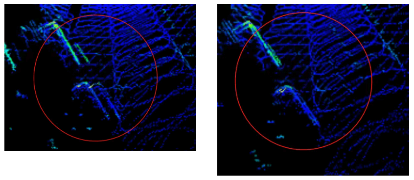
Figure 4 shows the results after point cloud calibration
III. Use of self-motion distortion calibration tool and instructions
We have uploaded the above distortion removal process code to GitHub, if you are interested, pleaseclick here.
Code notes:
Rely on:
livox_ros_driver
PCL
ROS
Compilation: Use commands under workspace
catkin_make
Run:
source develop/setup.bash
roslaunch livox_distribution_pkg run.launch
Interface notes:
ImuProcess class is defined in data_process.h. The member function UndistortPcl of this class is de-distortion function, the function parameter Sophus::SE3d Tbe is the location between current frame point cloud frame head and frame tail, if the location can be provided directly, then the function can be called for distortion removal. If only IMU data is available, Process - the member function of ImuProcess is called for distortion removal.
Special notes:
The calibration of offset distortion requires the user to manually calculate the offset change under the corresponding time difference according to their respective offset information sources (GPS position coordinate, speed, etc.) and input it as the function UndistortPcl in the code.
Use:
Input:
This tool is developed from ros, so the input information has two topics, the point cloud topic is /livox/lidar, customMsg format, and the IMU information topic is /livox/imu
Output:
The output is the calibrated point cloud /livox_unidistort
一 什么是激光雷达自运动畸变 激光雷达通过发射激光束来测量周围环境物体的距离和方位,从而判断车辆与障碍物的相对位置。当其发射的激光束足够多时,这一个个的激光点将汇集成一片点云,勾勒出其所处的三维环境信息,这便是我们常说的点云数据。
对于多数激光雷达而言,尽管激光的发射与接收很快,但构成点云的每一个点仍非同一时刻生成的。一般我们会将100ms (对应典型值10Hz) 内累积的数据作为一帧点云输出。若在这100ms内,激光雷达本体或安装所在的机体发生绝对位置的变化,那么此帧点云中每一个点的坐标系就是不同的。直观上看,这一帧点云数据就会发生一定的“变形”,不能真实对应所探测到的环境信息,类似于拍照时手抖了,拍出来的照片就会糊。这便是激光雷达的自运动畸变。
二 自运动畸变产生的本质以及校正
我们来具体看一看自运动畸变是什么样的。 激光雷达点云自运动畸变的形态,与其扫描方式是相关的。比如传统360度机械式激光雷达每一帧,是以雷达为中心环绕扫描一周(100ms)得到的。当雷达本体或所在车体静止时,扫描起始点和终止点可以比较好地闭合(坐标原点始终保持不变)。而当雷达或自车运动时,自运动畸变就会发生,环绕一圈的数据就会发生扭曲,导致环绕不再闭合(不同点的坐标原点不同)。
下面我们再深入分析一下这一现象的本质。
简单来说,激光雷达点云自运动畸变的产生本质上是一帧中每一个点的坐标系不同。 如下图,左图p1~p3表示激光雷达依次扫描到的三个位置点,这三点在真实世界中共线。但由于激光雷达自身在一帧时间内存在“剧烈”运动,如中间图所示,雷达自身分别在三个不同的实际姿态下对三个点进行了扫描。因此在最后得到的点云中(最右图),三个点坐标实际处于不同的坐标系,看起来不再共线了。
图2 点云坐标系发生变化 图3也给出一个实际应用的例子。
搭载Livox激光雷达的车辆因自身掉头发生了自运动畸变:远处的墙体和车辆都因为自车快速旋转产生了分层现象。
图3 由于车体运动,路边停放的车辆点云出现分层
那么,自运动畸变要怎么校正呢?显然,只要我们把车开得足够的慢…… 当然不是,只需要我们将这一帧内所有点的坐标系都转换到同一个,如图1 第一个点 p1 所在的雷达坐标系,这本质上就是对雷达的运动进行补偿。
原理上看起来非常简单(实际也非常简单)。只要知道每个点的T1i就行了,那到底怎么知道呢?
在实际应用中,一般首先设法测量激光雷达的运动信息,如一帧点云首尾(100ms间隔)的雷达位姿变化 T。然后根据某点到初始点或末尾点之间的时间差 Δt,通过短时匀速假设进行线性插值得到该点的 。
位姿变化 T 可通过惯性导航系统(INS)或激光雷达里程计(LiDAR Odometry, 如 LIO-Livox)提供的位姿信息获得。若使用惯性测量单元(IMU,可提供角速度以及加速度信息)计算位姿变化,则需要额外提供雷达或者自车的初始速度信息。
那 Δt 的值怎么获得呢? Livox 激光雷达输出自带每个点的时间戳。在获取点云的时候就可从点云数据包 Custom Msg中直接读取到。而其他雷达则可能需要根据各自雷达的 SDK 所提供信息或自行手动解算得到每个点的时间戳。
按上述公式将各个点坐标转换到同一坐标系,就是去畸变的过程了。 下图4 展示了去畸变前后的点云对比。
图4 点云校正后效果对比
图5 道路两旁建筑点云畸变前后对比:彩色点云为原始点云,白色点云为校正后点云
三、自运动畸变校正工具使用及说明 上述去畸变的过程代码已上传 Github, 有兴趣的读者欢迎点击下方链接查看。 https://github.com/Livox-SDK/livox_cloud_undistortion
代码说明: 依赖:livox_ros_driver,PCL,ROS编译:在工作空间下使用指令 catkin_make运行:source devel/setup.bashroslaunch livox_dedistortion_pkg run.launch接口说明:
在 data_process.h 中定义了 ImuProcess 类,该类的成员函 数UndistortPcl 为去畸变函数,该函数参数中 Sophus::SE3d Tbe 为当前帧点云帧头和帧尾之间的位姿,如果可以直接提供该位姿,则可以调用该函数进行去畸变。如果只有IMU数据,则调用 ImuProcess 的成员函 Process 进行去畸变。
使用: 输入:此工具基于ros开发,因此输入信息为两个 topic,点云 topic 为 /livox/lidar, customMsg 格式,IMU 信息 topic为/livox/imu输出:校正后的点云 /livox_unidistort
特别说明:平移畸变的校正需要用户根据各自的平移信息来源(GPS位置坐标、速度等)手动计算对应时间差下的平移变化,作为UndistortPcl输入。
|


 Posted on 2021-11-29 12:25:05